Archives 2023

DHCP Option 82 and the endless possibilties

DHCP Option 82 and the endless possibilties

Recently, the development team at OpenWiFi has added a DHCP-Relay feature to the OpenWiFi firmware. I worked with the Q&A team to come up with a test plan for the feature. At first it sounded straight forward. All we have to do is capture the DHCP request packets leaving the AP and verify whether they are sent out as broadcast or unicast. The other aspect we needed to verify was that under option 82 the development team allowed for 3 values to be forwarded to the DHCP server under the 1st and 2nd sub-options, (Agent Circuit ID and Agent Remote ID) the SSID, the VLAN, or the AP MAC address but, this could also be verified with the same simple Wireshark capture.

This is all good but, is it enough? Does that mean that the DHCP-Relay will work as a part of an ecosystem? Will the DHCP server recognize the information sent under option 82 and filter clients accordingly ? Those questions made me realize that a simple capture is insufficient to guarantee whether or not this new feature actually works. We needed to come up with a scenario where this feature is tested under real world conditions. A test plan that mimics how this feature will be used in the field.

But, first let’s take a step back and refresh our memory on what does a DHCP Relay do and why is it important ? For a client to obtain an IP from a DHCP server it has to go through the DORA frame work.

The process starts with broadcasting a Discover packet with a destination address 255.255.255.255. If there is an active DHCP sever on the same VLAN or subnet it will reply with an Offer message and the client and server go through the DORA framework. However, sometimes the DHCP server is on a different VLAN or sets in the cloud serving many locations at once. We all know that broadcasts are dropped by the routers so how can a client reach a DHCP server that doesn’t live on the same subnet. This is where the DHCP-Relay comes into play. The DHCP-Relay intercepts the Discover packet and transform it on behave of the client from a broadcast to a unicast that targets a specific preconfigured DHCP server.

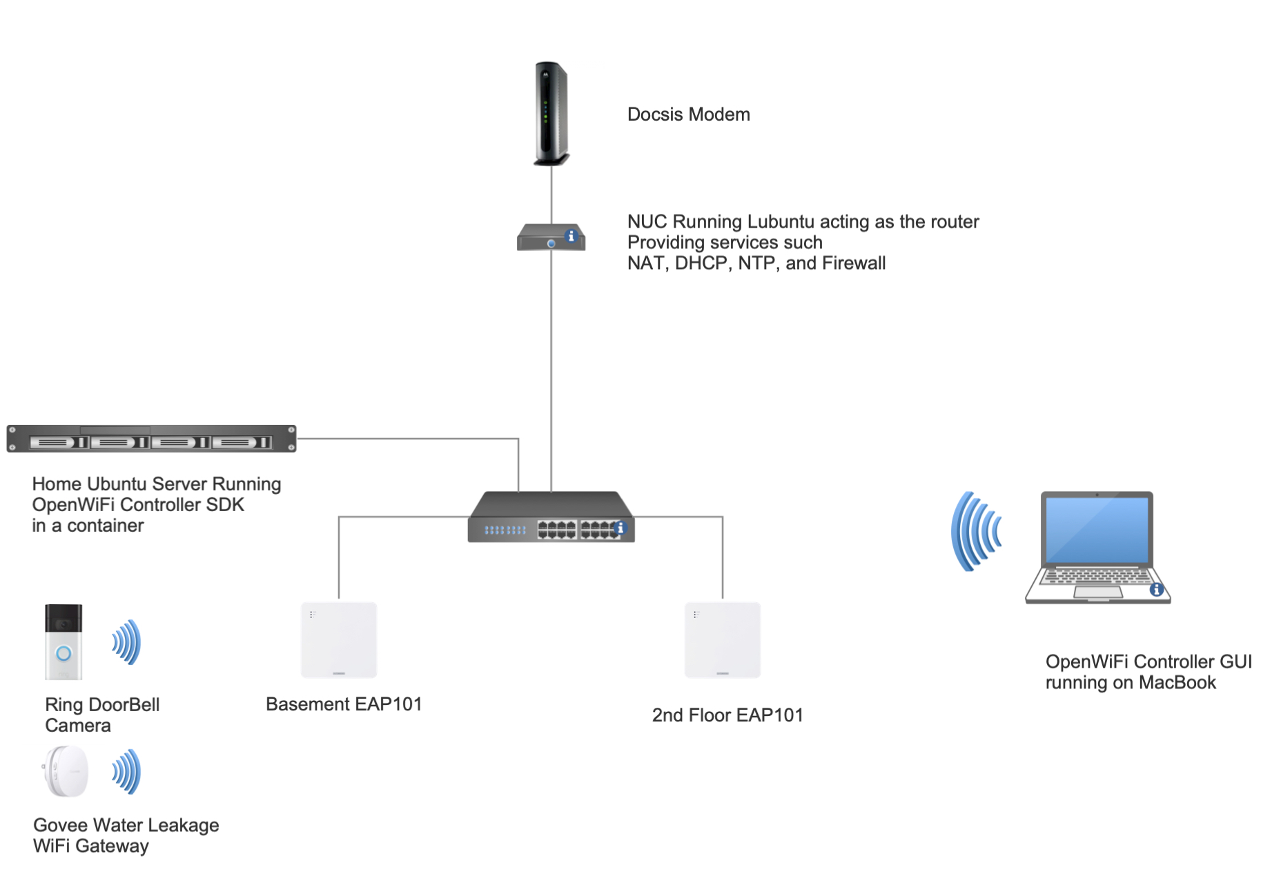
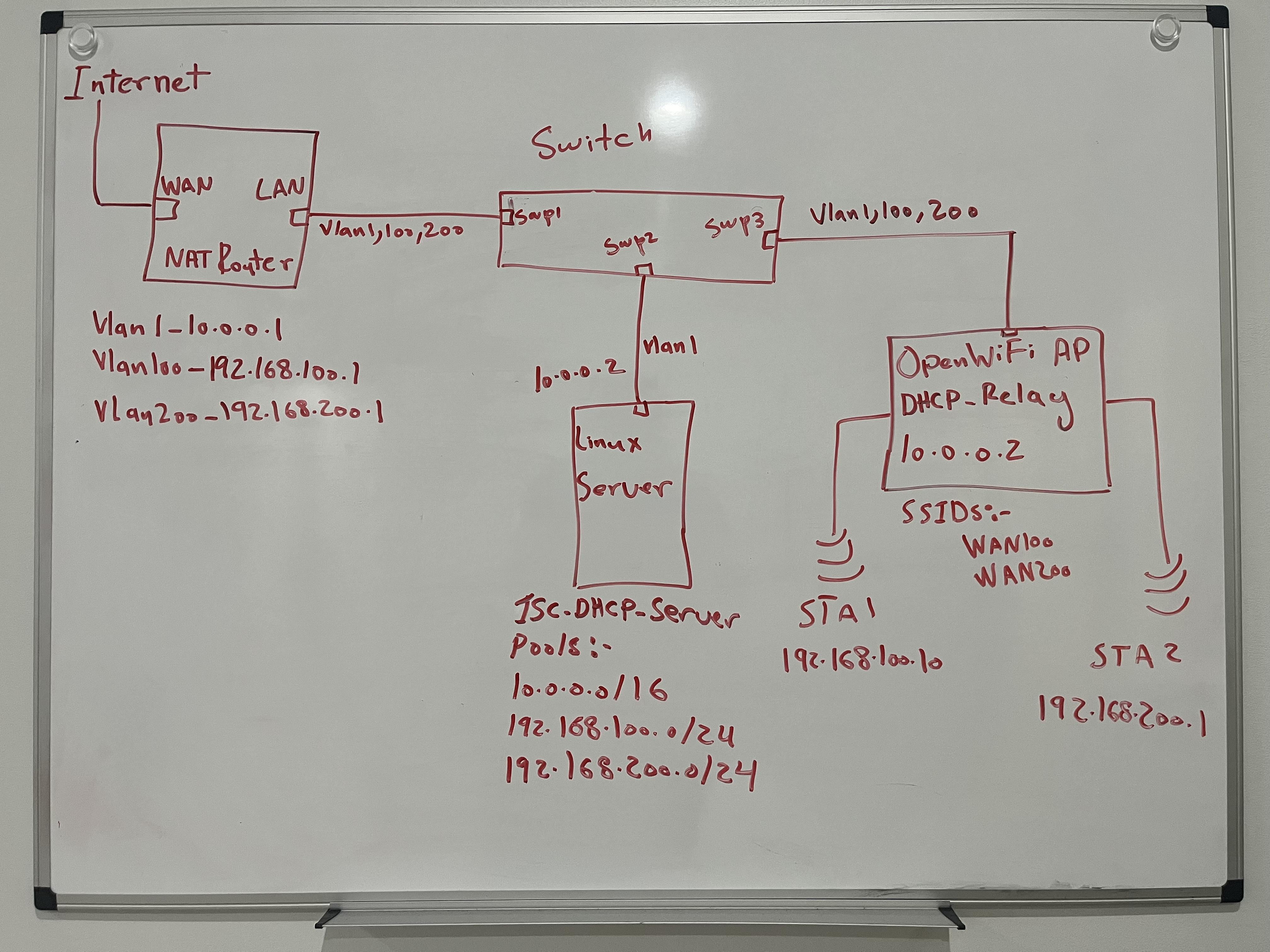
Considering all of the above, it was time to get to the whiteboard. I decided to use my home network as the ground for testing. My home router which is just an Ubuntu NUC running linux will act as the NAT router for 2 new VLANs 100, and 200 (along side my native VLAN subnet 10.0.0.0/16 that I use for my home devices and AP and switches management interfaces). My Ubuntu server will provide DHCP pools for the 2 new VLANs through ISC-DHCP-Server service. I needed a switch to tie it all together so I bought a managed L3 TP-Link switch (TL-SG2008P). I created VLANs on it and connected everything together.

I configured the OpenWiFi AP to act as the DHCP-Relay for any clients connected on the 2 SSIDs I created, WAN100 and WAN200 (WAN100 -> VLAN100, WAN200-> VLAN200). I also configured the DHCP-Relay to include the SSID name under the 1st sub-option of option 82. The reason for that is to use this piece of information as the basis for filtering. The DHCP server will decide on what pool should the clients gets its IP from.

The real challenge laid with understanding and configuring the ISC-DHCP-Server to distinguish between the different request and assign the correct IP address.

I created 2 classes to filter sub-option1 under DHCP option 82. I used the allow and deny statement to filter which pool should serve each VLAN. I deep dove into the packet capture to find out the offset and length of the information included in sub-option 1 to input the correct values for the match if condition statement. This required a capture of the unicast DHCP Discover packet and finding out the number of bytes included in the sub-option.

It can be seen in the screenshot above the total number of highlighted bytes are 8 and the offset is 0 since we started counting from the first received byte.

All was left now if to create 2 STAs and connect each one to a different SSID on the AP and hope they get the correct IP addresses. I took me around 3 days to perfect the setup but at the end the 2 virtual STAs I created on my Candela LANforge box acquired the correct IP addresses with respect to the SSIDs they were connected to.

The 2 highlighted STAs wlan0 and wlan1 are shown to be connected to their respected SSIDs and the IP addresses match the pools assigned to those SSIDs.

The DHCP-Relay feature combined with the ability to filter based on the information included in option 82 on the DHCP server side opens up countless opportunities for different deployment scenarios. Clients can identified and assigned to specific pools based on many different aspects. For example, one can include the AP MAC to differentiate clients based on their physical location, or assign variable lease times based on whether this is a guest or employee VLAN.

DHCP issues with IoT devices?  How the misbehavior of few IoT devices made me appreciate OpenWiFi more

DHCP issues with IoT devices?  How the misbehavior of few IoT devices made me appreciate OpenWiFi more

As a new fan for home automation, I’ve recently started a journey to install several IoT devices that improve the convenience and effectiveness of my daily life. 95% of those devices are 2.4GHz only, which has a unique set of challenges to begin with. A few of the gadgets I have so far installed are a Govee water leak detector, a Ring Amazon Camera, and TP-Link light switches and plugs. Unfortunately, when Proxy-ARP was enabled on my personal OpenWiFi APs setup, I had an issue where some IoT devices were unable to receive IP addresses.

The Govee Wi-Fi gateway and the Amazon Ring Camera were the main devices that displayed the IP address acquisition problem in the presence of active Proxy-ARP functionality on the AP. Understanding how devices behave during the IP acquiring process is crucial for identifying the root cause of this issue.

When an IoT device (or just any device for that matter) connects to a network, it requests an IP address from the network’s DHCP server. To ensure that the IP address it receives is available for use, the device sends a special type of ARP (Address Resolution Protocol) called the DHCP ARP Probe to check if any other devices on the network are using the same IP address. The expectation is that if the IP address is free, no response will be received, indicating its availability. The device may, however, think the IP address is already in use if it receives a response to its ARP Probe and declines the DHCP offer.

The IoT devices’s misbehavior manifests when Proxy-ARP is enabled on the AP. In this scenario, when an IoT device sends an ARP probe to validate IP address availability, the access point responds on behalf of the device. However, the IoT device fails to recognize that the MAC address in the response from the Proxy-ARP is its own.

As a result, the IoT device mistakenly believes that the IP address it acquired from the DHCP server is already in use since it receives a response to its ARP probe. Consequently, the device declines the DHCP offer, causing it to fail in acquiring an IP address and establishing connectivity.

As it can be seen in both packet captures for the Amazon Ring Camera and the Govee WiFi Gateway, both devices decline the DHCP offer after receiving an ARP response to the ARP probe of the offered IP address by the DHCP server.

On the other hand, the remaining devices (about 45 devices from different vendors) on both the 5GHz and 2.4GHz bands recognize the MAC addresses in the responses as being their own MAC addresses and accept the DHCP IP offers. When the Proxy-ARP capability is enabled, an iPhone 13 in the example below behaves as predicted.

Disabling the Proxy-ARP feature on the 2.4GHz SSID (as 90% of IoT devices can only operate on 2.4GHz) was the simplest and most direct solution to the issue. it worked… in my relatively quiet 2.4GHz home environment but, do I really want to compromise a topology design because of couple of misbehaving clients? and I can only picture the AirTime utilization nightmare that would arise in a larger, industrial, and much noisy environment.

I wanted to conduct one more test to further my conviction that this is a device-specific issue, which I was 99% certain of at this time. To my amazement, the Ring Camera functioned flawlessly with Proxy-ARP enabled on the SSID when I tested it against a Ruckus R730 AP that I had lying around. This prompted me to return to the drawing board and think about additional key factors that may have influenced the issue on the AP side.

Reading about how Proxy-ARP is implemented in OpenWiFi (or, to be more precise, the Linux kernel) and discussing the issue with the community. We uncovered that the ARP bounce-back capability is enabled by default in the Linux Kernel. This meant that the Kernel was replying back to the source of the ARP Probe and telling them they are the owner of that MAC address. Now all I had to is to disable that feature in the Kernel and Ring Camera should work with Proxy-ARP enabled.

Disabling the a feature in Kernel’s and building a new functional image may sounds like a tremendous task to take on that could weeks or even months. Imagine all the support nightmare you will have to go through with a vendor to just get such a fix included in their next release. The beauty of OpenWiFi being open-source is that you can easily reconfigure any fundamental functionality and create a new image to mitigate against any issues, like misbehaving clients for example. Utilizing the CICD pipeline of OpenWiFi to disable the ARP bounce-back feature in the Kernel, a new dev image with the Kernel ARP bounce-back feature set to disable from one of the program maintainers took only a few hours.

The fresh AP NOS image had the capacity to correct the misbehavior of a few IoT devices while utilizing less AirTime since I was able to enable the Proxy-ARP capabilities. While it fixed the issue, I wanted to also make sure there are no unintended consequences.  Running the new image through out nightly open-source 5000 test cases ensued that I had a stable image that is ready for deployment.

My objective when begin to write the article was to present an interesting technical case that could potentially save someone from losing a few days of their life attempting to troubleshoot it. By the time the draft was finished, I could clearly see how the message had evolved to emphasize how this case demonstrates the strength and potential of OpenWiFi and its transformative open and collaborative lifecycle, which gives everyone a voice, the power to directly affect and prioritize roadmaps, and the agility to ensure the stability of the ecosystem.

Screenshots of the packet capture with Proxy-ARP functionality is disabled on the 2.4GHz SSID. The IoT devices tend to send around 3-4 ARP Probes before it declares to the network over an ARP announcement that it has updated it is IP address.

Why choose a 4×4 AP over a 2×2 one ?

Why choose a 4×4 AP over a 2×2 one ?

In today’s market, 2×2 APs are widely available, and several suppliers promote them as a less expensive, high-density deployment-capable alternative to the 4×4. On paper, 2×2 APs can theoretically offer a 2×2 client the same throughput numbers as a 4×4 one, which makes them more desirable.

The actual query is, in practice, do they realistically offer a 2×2 client the same throughput numbers? I’ve always known by heart that, a 4×4 AP has about 3dB of beam-forming gain on the downlink because of the two extra chains, and 3dB of gain on the uplink because of the MRC gain of the extra chains. That sounds wonderful, until you have to explain to someone why they should choose the more expensive 4×4 AP over the less expensive 2×2 AP when the manufacturer has assured them that the 2×2 AP can manage high density installations and can offer the same throughput numbers to a 2×2 client.

I start seeking for scientific evidence to back up my argument that in real life scenarios, a 4×4 AP is superior to a 2×2. During my research, I stumbled across Wes Purvis’ outstanding talk from the 2018 WLPC in Phoenix. Wes went on to demonstrate that a 4×4 had a gain over a 3×3 AP of roughly 2.4dB on the downlink and 1dB on the uplink. In multi-client scenarios, this resulted in a 15% increase in data rate and a 10% increase in throughput.

I was content with what I had discovered up until this point, but not quite. After all, this demonstrates that a 4×4 is superior to a 3×3, but not superior to a 2×2. What if the odd number of antennas is to blame for the 3×3’s subpar performance? The question might seem absurd or strange to us wireless engineers, but it is an illustration of the kind of inquiry non-technical management might ask you in an effort to comprehend why you selected the more expensive 4×4 AP.

As a result, I carried out more research and discovered this fantastic Matlab work that described how to demonstrate the advantages of beam-forming from a 4×4 AP to a 2×2 client over using techniques such spatial expansion.
https://www.mathworks.com/help/wlan/ug/802-11ac-transmit-beamforming.html?fbclid=IwAR2ZBkgO_NV4Fz4e0-qwR7dmGusgv6fen9pRoLVnIQSbDpMx-rON799OOQo#responsive_offcanvas

I hypothesized that by just changing the number of transmitting antennas from 4 to 2, I could use the same illustration to demonstrate how beam-forming from a 4×4 AP to a 2×2 client is superior to beam-forming from a 2×2 AP to a 2×2 client. I executed the code twice under identical setup conditions, first for the case of 4×4=>2×2 and a second time for the case of 2×2=>2×2.

The setup evaluated a 2 spatial streams transmission using MCS4 on a 20MHz BW and TGac channel model with a Model-B delay profile from the AP to a client at a distance of 100 meters.

 4×4=>2×2 SS12×2=>2×2 SS14×4=>2×2 SS22×2=>2×2 SS2
EVM RMS2.0%4.7%4.1%8.4%
EVM dB-33.9-26.5-27.7-21.5
Error Vector Magnitude values for SS1 and SS2 for the 4×4=>2×2 and the 2×2=>2×2
Constellation patterns for spatial 1 and 2 in the case of beam-forming from a 4×4 AP to a 2×2 client.

Constellation patterns for spatial 1 and 2 in the case of beam-forming from a 2×2 AP to a 2×2 client.

One can clearly see from the above results that the 4×4 AP had a lower EVM values than the 2×2 AP. This would lead to improved SNR values in real-world scenarios, which in turn would enable the 4×4 AP to shift gears and switch to a higher MCS rate.