Exploring QoS, Traffic Shaping, and AQM: Insights from Real-World Testing

As part of our ongoing research at 802.11 Networks, the team conducted an in-depth traffic shaping and QoS (Quality of Service) test to evaluate how different traffic prioritization strategies perform in real-world conditions. This research aims to help our customers better understand their networks and make educated decisions on configurations that ensure optimal performance.
Test Setup Highlights:
- Total Clients: 30
- Zoom Clients: 3 (Simulating Zoom calls with 3Mbps uplink and downlink traffic per client)
- Streaming Clients: 27 (Simulating video streaming with uplink traffic ranging between 128Kbps–2Mbps and downlink traffic between 1.5Mbps–30Mbps)
- Protocol: TCP
- Environment: OTA testing inside an RF isolation chamber for accurate and interference-free results
- Access Point: CIG WF196, running OpenWiFi v3.2.0
- Channel: 48/20MHz
- Average RSSI: -60dBm
- WAN Configuration: Simulated Cable Modem link using Linux TC, with 20Mbps uplink and 1000Mbps downlink to replicate a typical Comcast subscription
- AQM:
- FQ-CoDel
- CAKE
The test environment included a traffic generation server connected to the AP’s WAN link via a Linux box simulating the Cable Modem WAN link. This controlled environment allowed us to precisely measure the effects of various QoS configurations on network performance.
Test Cases Conducted:
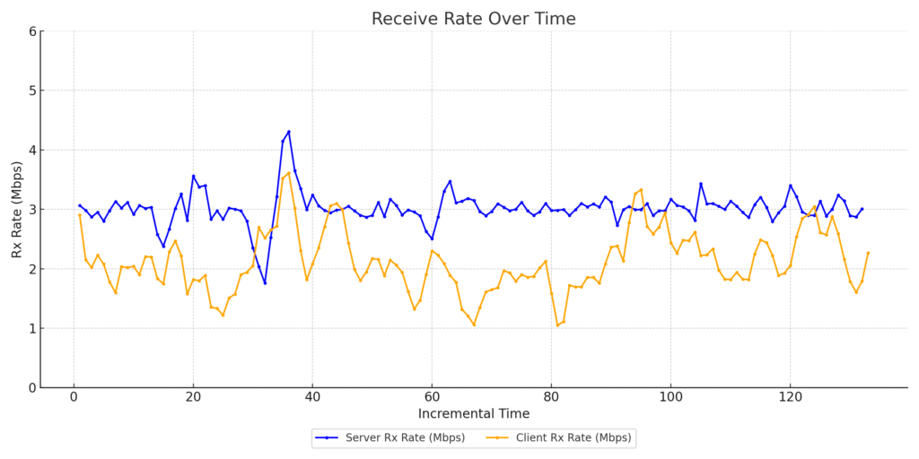
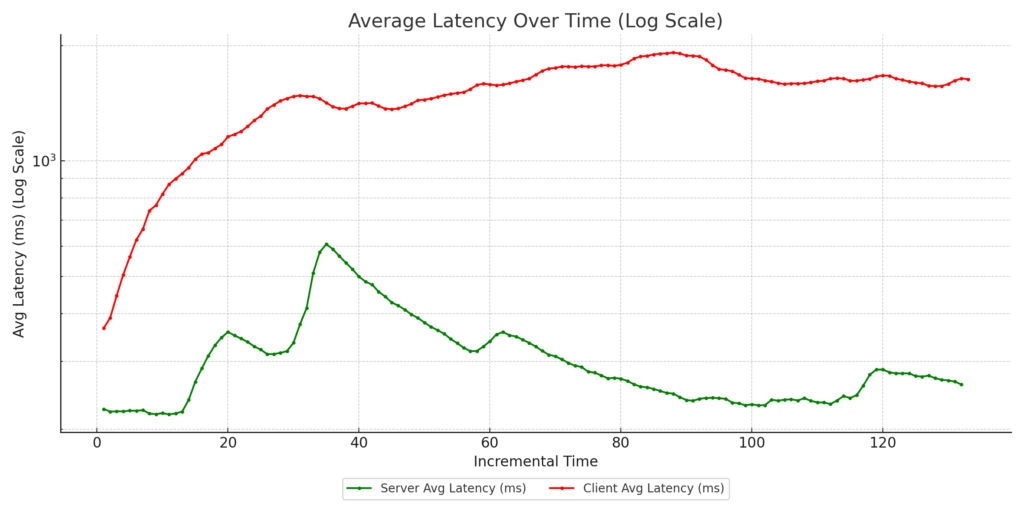
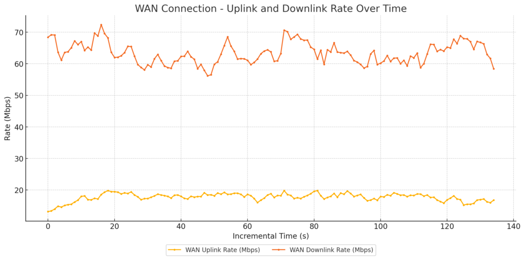
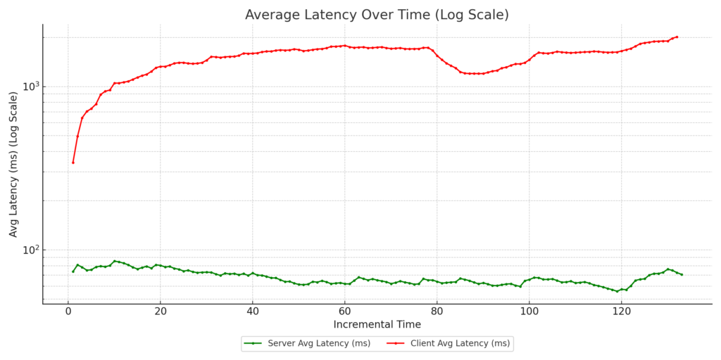
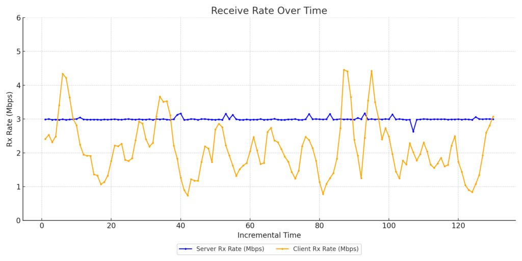
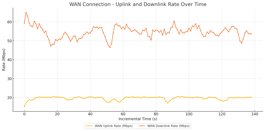
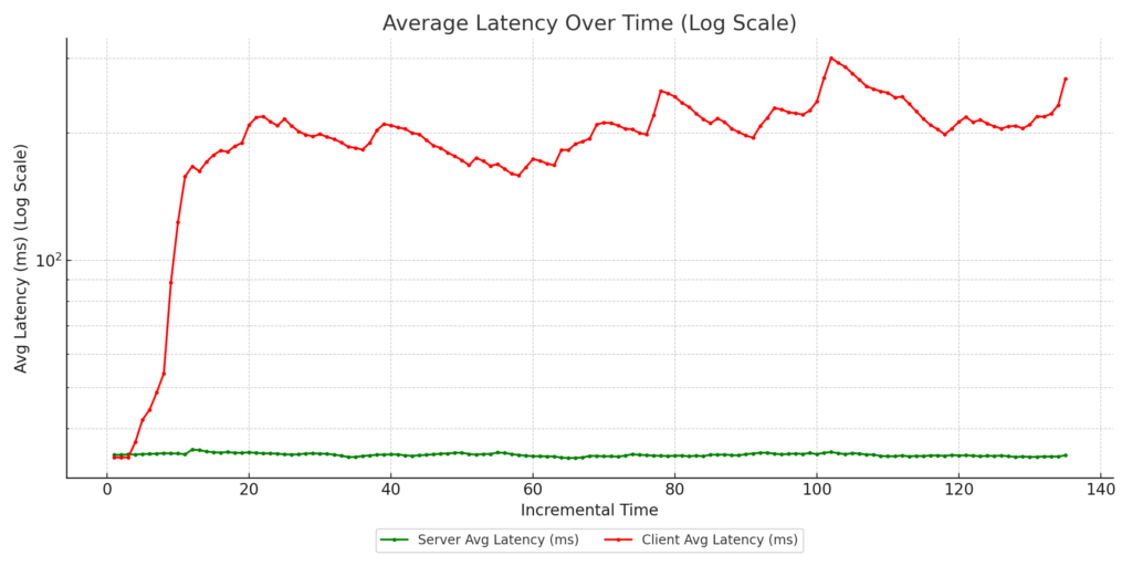
- FQ-CoDel with no DSCP marking: Default case with no configurations.
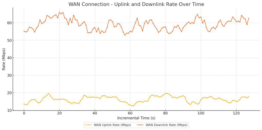
WAN link Traffic
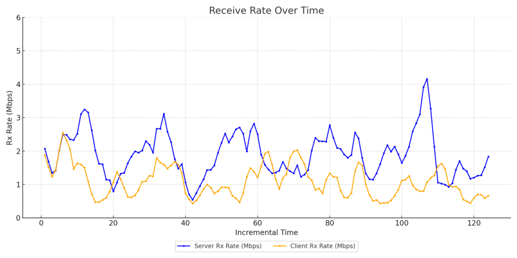
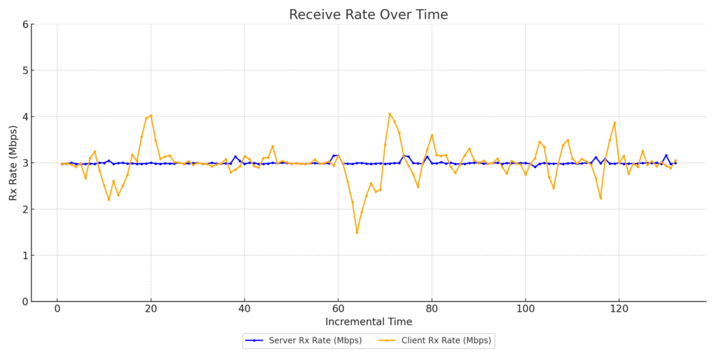
Zoom Client1 Throughput
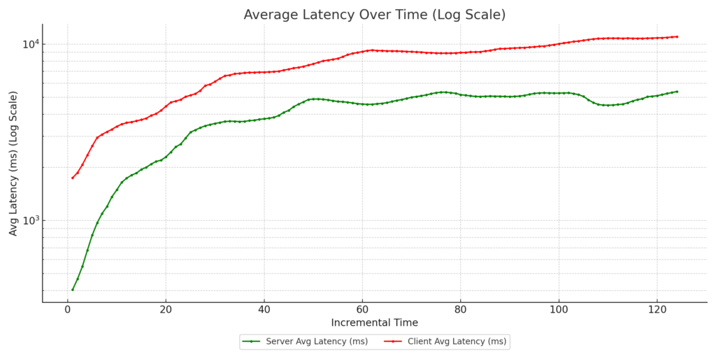
Zoom Client1 Latency
Zoom Client2 Throughput
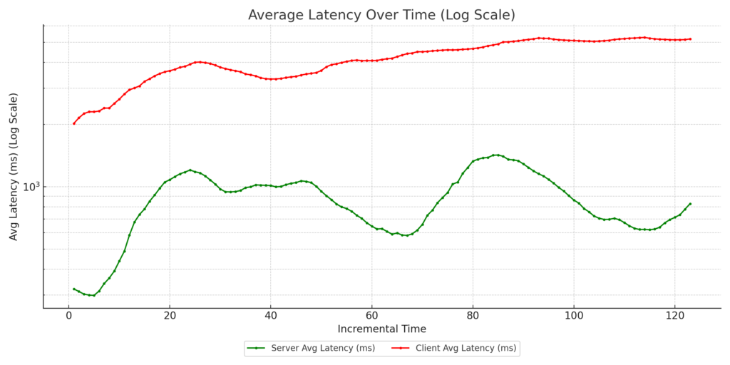
Zoom Client2 Latency

Zoom Client3 Throughput
Zoom Client3 Latency
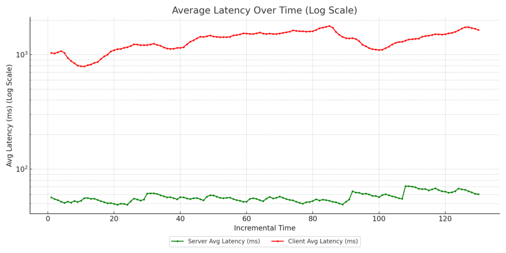
- FQ-CoDel with marked uplink: Zoom clients’ uplink traffic marked as video with DSCP CS4.
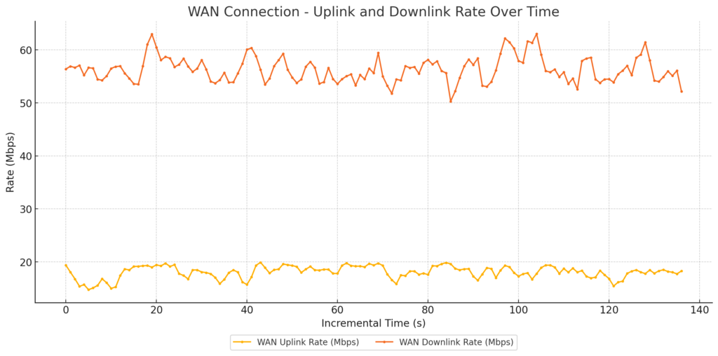
WAN Link Traffic
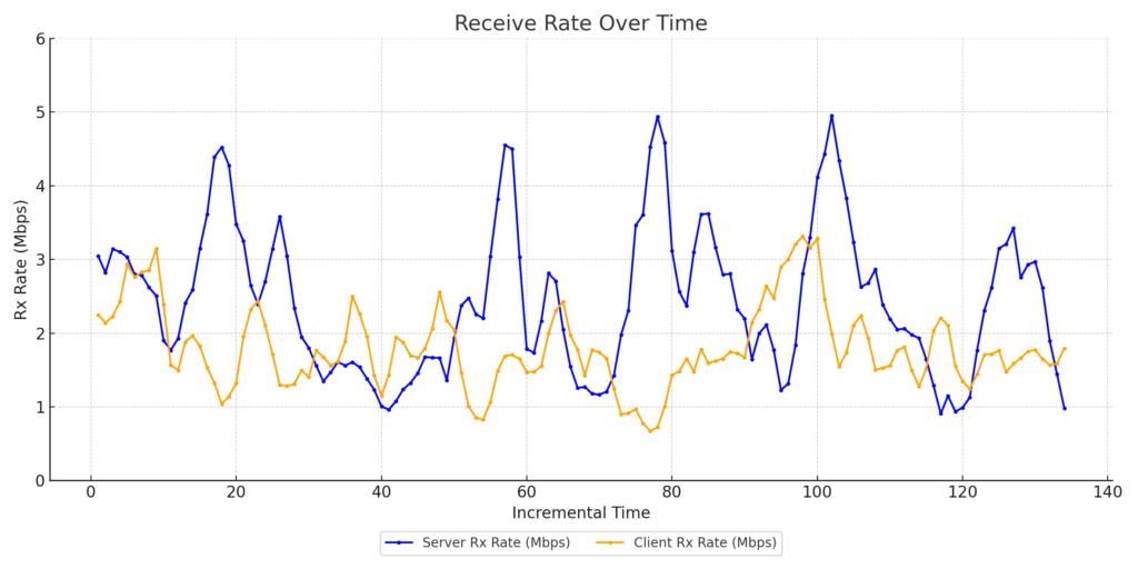
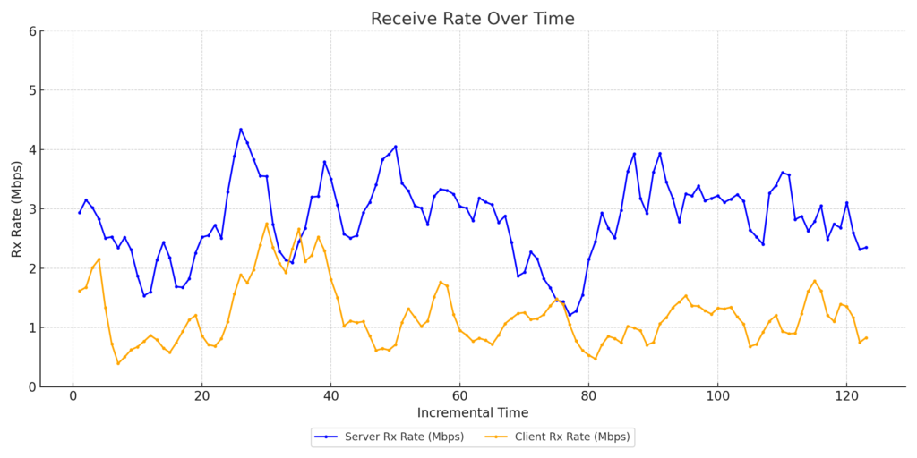
Zoom Client1 Throughput

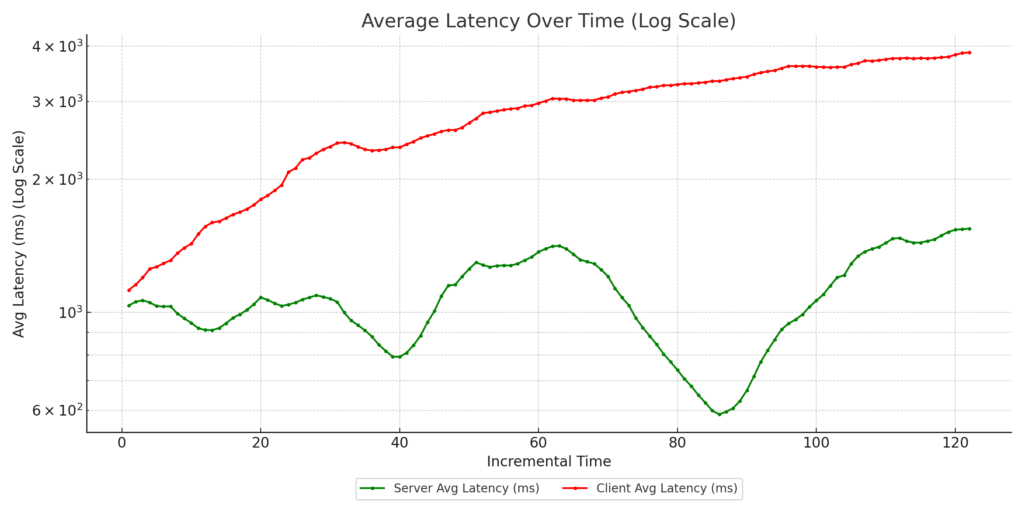
Zoom Client1 Latency
Zoom Client2 Throughput
Zoom Client2 Latency
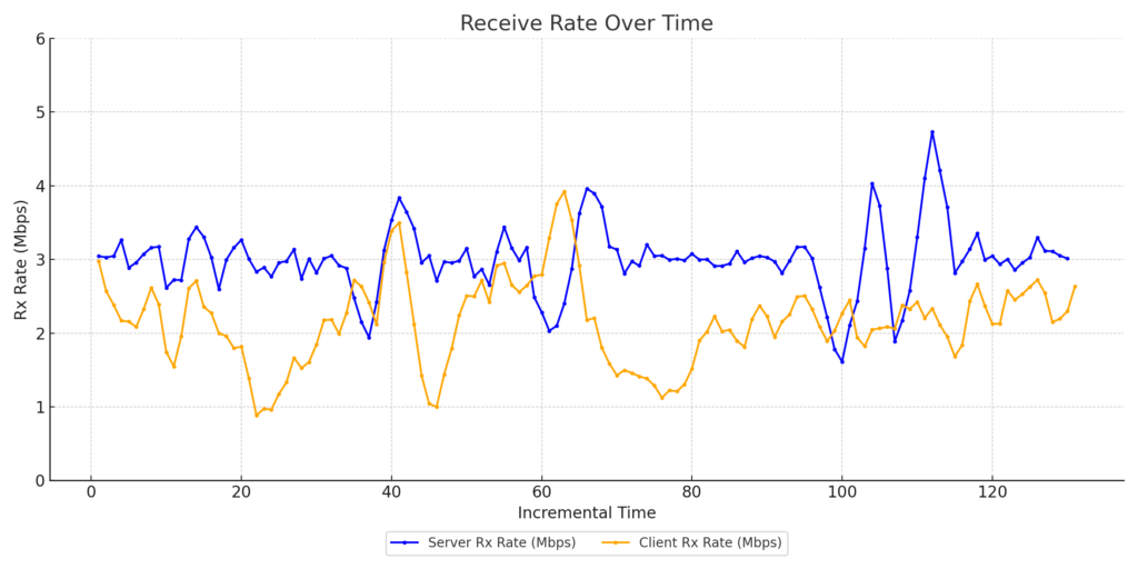
Zoom Client3 Throughput
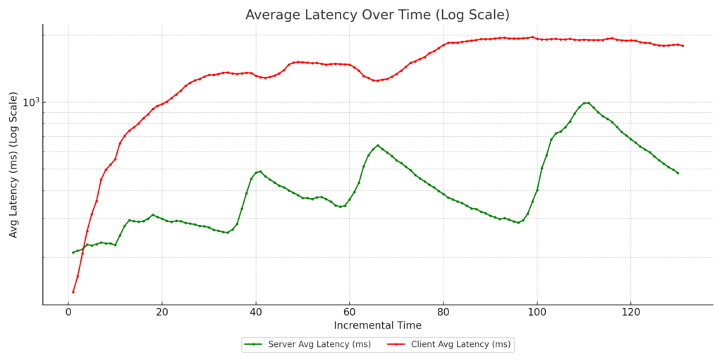
Zoom Client3 Latency
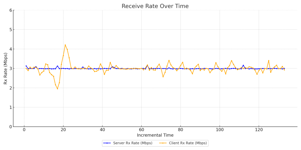
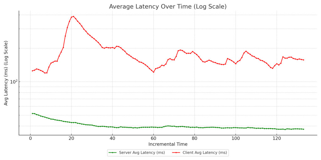
- CAKE with eBPF reclassification: No DSCP marking from side clients, but downlink traffic reclassified as CS5 using eBPF programs running in the AP kernel.
WAN Link Traffic

Zoom Client1 Throughput
Zoom Client1 Latency

Zoom Client1 Throughput

Zoom Client2 Latency
Zoom Client3 Throughput
Zoom Client3 Latency
- CAKE with eBPF reclassification + marked uplink : Zoom clients’ uplink traffic tagged with DSCP CS4, and downlink traffic reclassified as CS5 using eBPF programs on the AP kernel.
WAN Link Traffic

Zoom Client1 Throughput
Zoom Client1 Latency
Zoom Client2 Throughput
Zoom Client2 Latency
Zoom Client3 Throughput

Zoom Client3 Latency
In all test cases, 802.11e WMM was enabled on the AP to allow for hardware-assisted prioritization of traffic.
Key Takeaways:
- Case 4 consistently delivered the best results, with:
- Improved guaranteed throughput for the Zoom clients’ vs the streaming clients
- Reduced latency for Zoom clients, ensuring call quality
- These results highlight the power of combining advanced queuing mechanisms like CAKE with intelligent traffic classification using DSCP and eBPF.
Why This Matters: At 802.11 Networks, we specialize in wireless testing and performance optimization. This research underscores our commitment to helping customers achieve enterprise-grade performance using open-source hardware and intelligent network configurations. By understanding how QoS mechanisms like AQM, DSCP tagging, and WMM affect real-world traffic, network administrators can make informed decisions to enhance user experiences and ensure their networks perform at their peak.
If you’re interested in learning more about these tests or how they can be applied to your network, feel free to reach out or follow for updates.