As part of our ongoing research at 802.11 Networks, the team conducted an in-depth traffic shaping and QoS (Quality of Service) test to evaluate how different traffic prioritization strategies perform in real-world conditions. This research aims to help our customers better understand their networks and make educated decisions on configurations that ensure optimal performance.
Test Setup Highlights:
Total Clients: 30
Zoom Clients: 3 (Simulating Zoom calls with 3Mbps uplink and downlink traffic per client)
Streaming Clients: 27 (Simulating video streaming with uplink traffic ranging between 128Kbps–2Mbps and downlink traffic between 1.5Mbps–30Mbps)
Protocol: TCP
Environment: OTA testing inside an RF isolation chamber for accurate and interference-free results
Access Point: CIG WF196, running OpenWiFi v3.2.0
Channel: 48/20MHz
Average RSSI: -60dBm
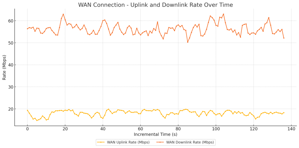
WAN Configuration: Simulated Cable Modem link using Linux TC, with 20Mbps uplink and 1000Mbps downlink to replicate a typical Comcast subscription
AQM:
FQ-CoDel
CAKE
The test environment included a traffic generation server connected to the AP’s WAN link via a Linux box simulating the Cable Modem WAN link. This controlled environment allowed us to precisely measure the effects of various QoS configurations on network performance.
Test Cases Conducted:
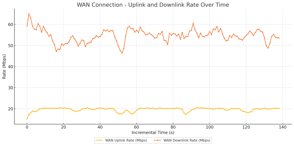
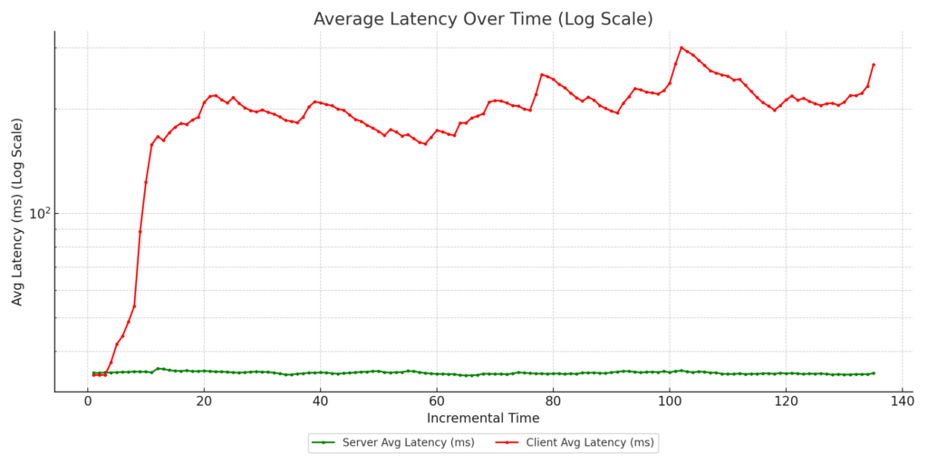
FQ-CoDel with no DSCP marking: Default case with no configurations.
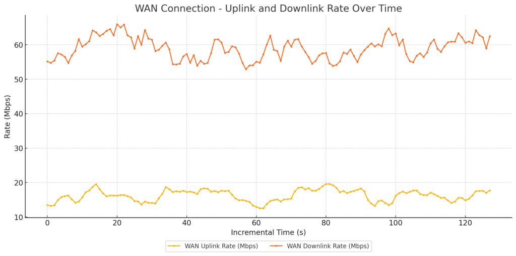
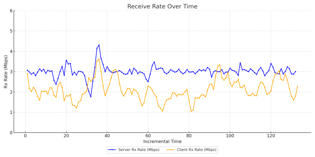
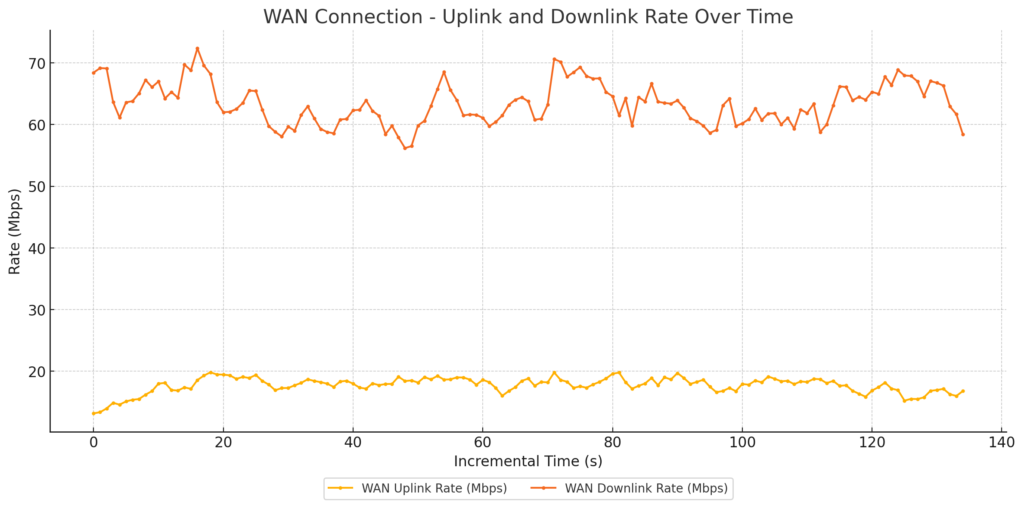
WAN link Traffic
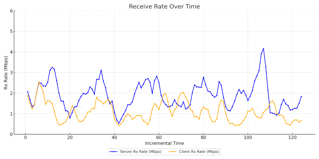
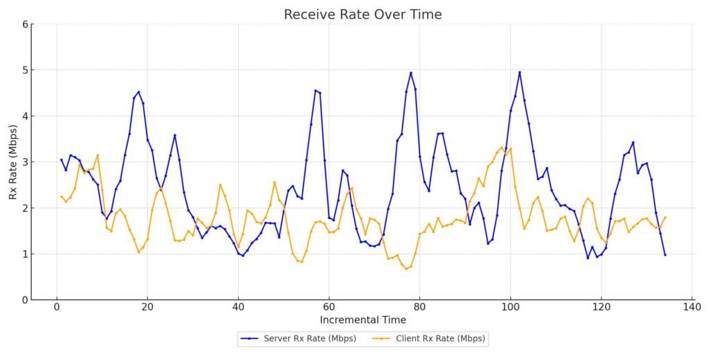
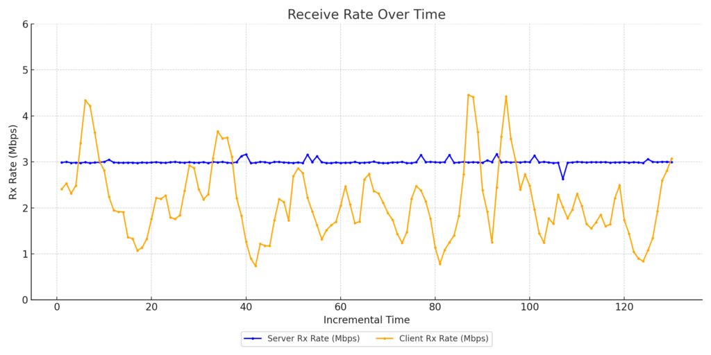
Zoom Client1 Throughput
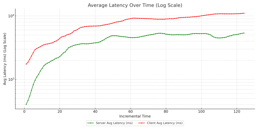
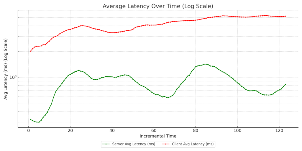
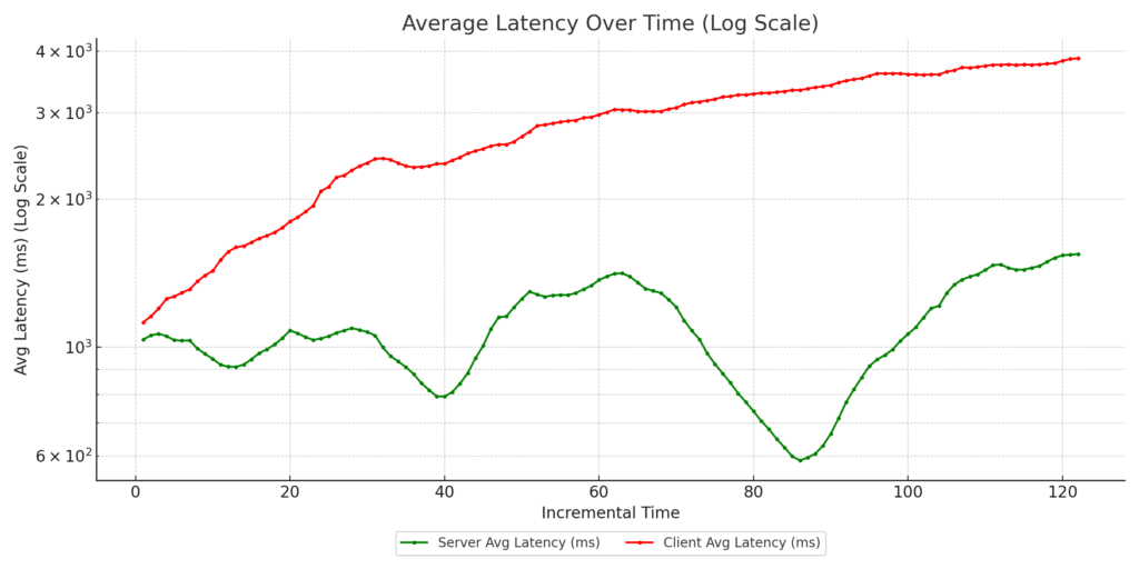
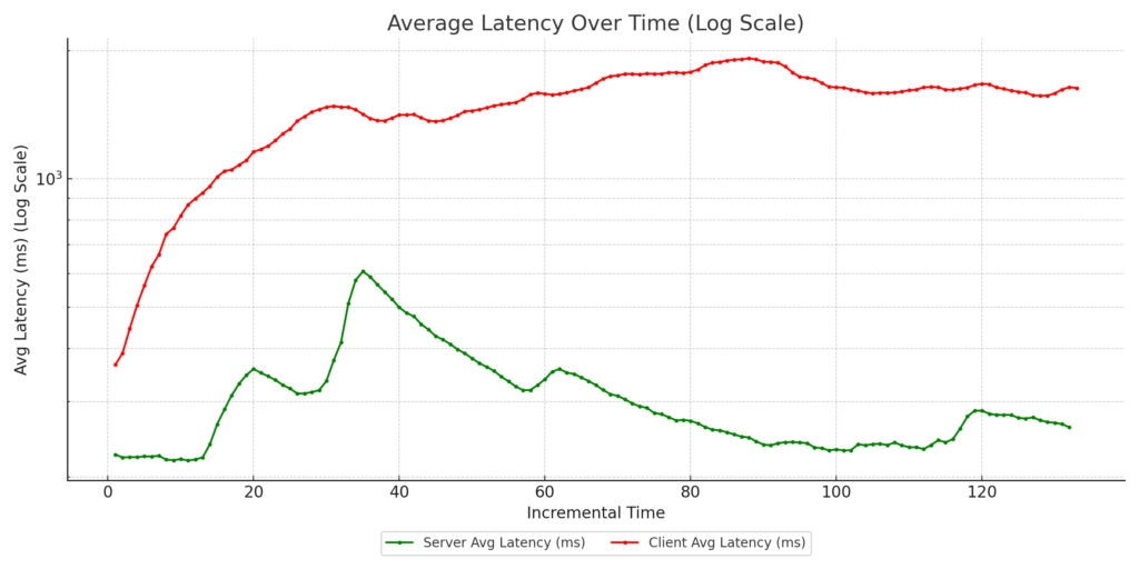
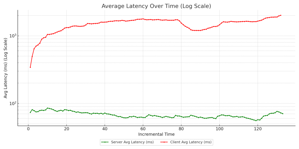
Zoom Client1 Latency
Zoom Client2 Throughput
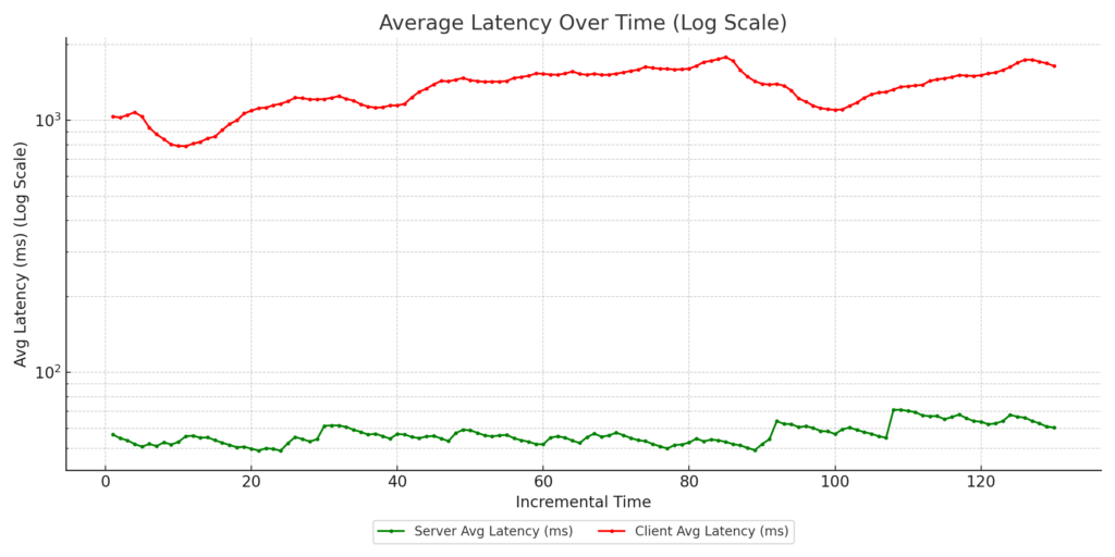
Zoom Client2 Latency
Zoom Client3 Throughput
Zoom Client3 Latency
FQ-CoDel with marked uplink: Zoom clients’ uplink traffic marked as video with DSCP CS4.
WAN Link Traffic
Zoom Client1 Throughput
Zoom Client1 Latency
Zoom Client2 Throughput
Zoom Client2 Latency
Zoom Client3 Throughput
Zoom Client3 Latency
CAKE with eBPF reclassification: No DSCP marking from side clients, but downlink traffic reclassified as CS5 using eBPF programs running in the AP kernel.
WAN Link Traffic
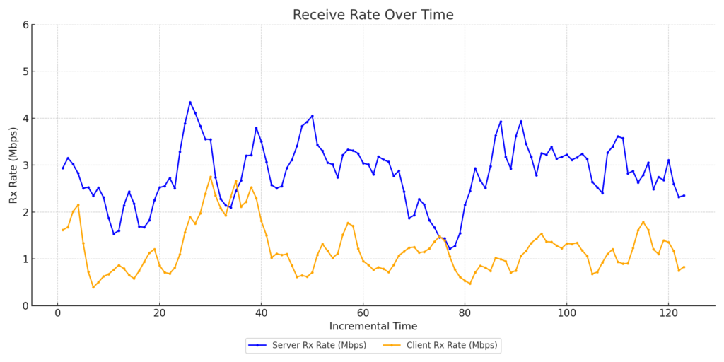
Zoom Client1 Throughput
Zoom Client1 Latency
Zoom Client1 Throughput
Zoom Client2 Latency
Zoom Client3 Throughput
Zoom Client3 Latency
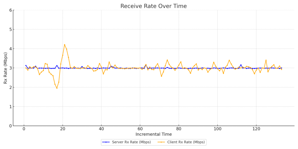
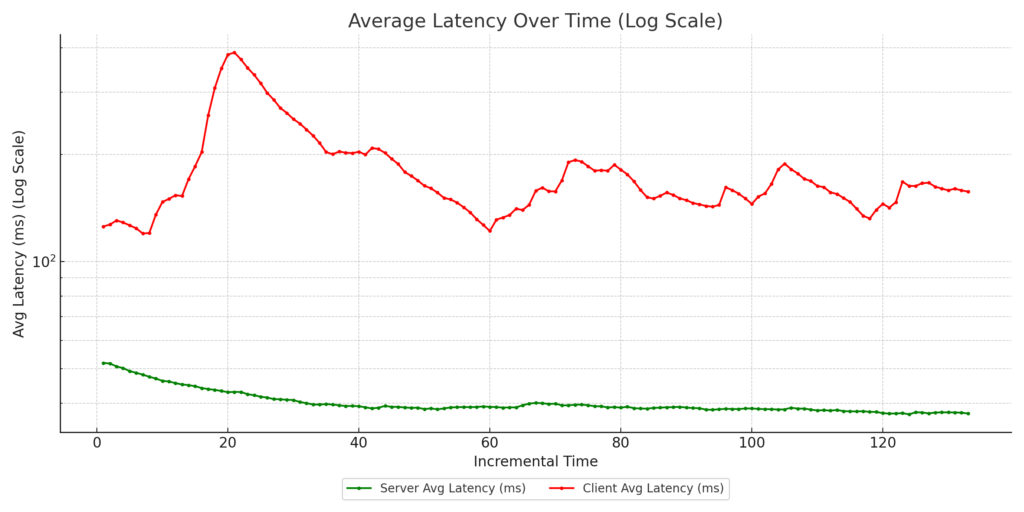
CAKE with eBPF reclassification + marked uplink : Zoom clients’ uplink traffic tagged with DSCP CS4, and downlink traffic reclassified as CS5 using eBPF programs on the AP kernel.
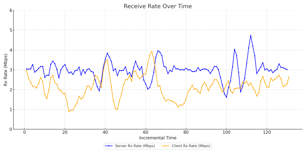
WAN Link Traffic
Zoom Client1 Throughput
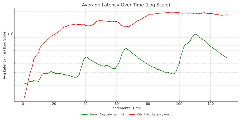
Zoom Client1 Latency
Zoom Client2 Throughput
Zoom Client2 Latency
Zoom Client3 Throughput
Zoom Client3 Latency
In all test cases, 802.11e WMM was enabled on the AP to allow for hardware-assisted prioritization of traffic.
Key Takeaways:
Case 4 consistently delivered the best results, with:
Improved guaranteed throughput for the Zoom clients’ vs the streaming clients
Reduced latency for Zoom clients, ensuring call quality
These results highlight the power of combining advanced queuing mechanisms like CAKE with intelligent traffic classification using DSCP and eBPF.
Why This Matters: At 802.11 Networks, we specialize in wireless testing and performance optimization. This research underscores our commitment to helping customers achieve enterprise-grade performance using open-source hardware and intelligent network configurations. By understanding how QoS mechanisms like AQM, DSCP tagging, and WMM affect real-world traffic, network administrators can make informed decisions to enhance user experiences and ensure their networks perform at their peak.
If you’re interested in learning more about these tests or how they can be applied to your network, feel free to reach out or follow for updates.
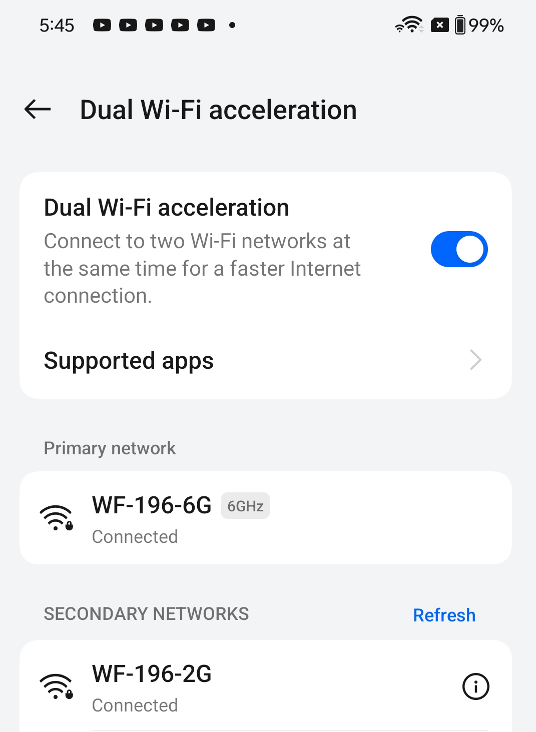
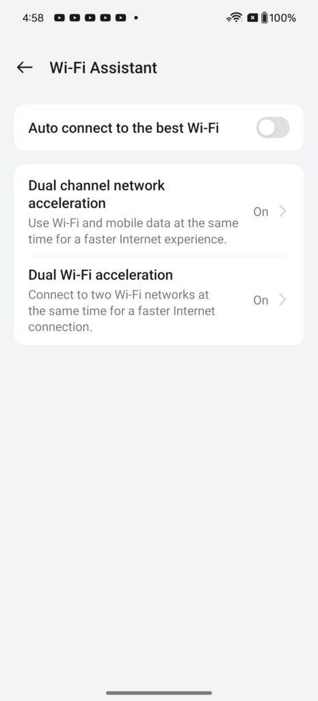
The OnePlus 12 offers a feature called “Dual WiFi Acceleration” under the WiFi Assistant page, claiming to achieve faster internet speeds by connecting to two WiFi networks simultaneously.
To evaluate this claim, I set up an OpenWiFi CIG WF-196 AP, a 4×4 WiFi 6e access point (AP) with support for 160MHz bandwidth on 6GHz, 80MHz on 5GHz, and 40MHz on 2.4GHz. I configured distinct SSIDs for each band:
WF-196-6G for 6GHz on channel 33 with 160MHz bandwidth
WF-196-5G for 5GHz on channel 116 with 80MHz bandwidth
WF-196-2G for 2.4GHz on channel 1 with 40MHz bandwidth
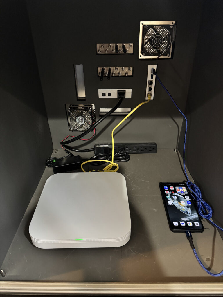
To maximize performance, I paired the OnePlus 12 with the AP using the 6GHz and 2.4GHz bands within an RF isolation chamber.
Although the OnePlus 12 is WiFi 7-capable, this setup does not leverage Multi-Link Operation (MLO). Instead, the phone establishes two separate physical connections over different radios. It appears to use some sort of load-balancing algorithm to optimize throughput across both links.
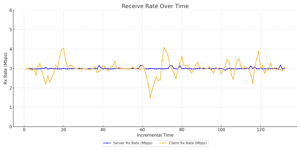
Using ADB commands and screen mirroring, I ran a speed test to a local Open SpeedTest server hosted on my router. In the video below, you can see how the phone successfully establishes two physical connections, one on wlan0 and the other on wlan1. The “iw dev wlan0/1 link” command outputs, refreshed every second, display packets sent and received over both interfaces.
However, the results were somewhat underwhelming. While the phone successfully maintained connections on both the 6GHz and 2.4GHz bands, traffic was rarely transmitted over both bands simultaneously. As shown in the video, almost all packets during the speed test were sent and received on the 6GHz link.
Another noteworthy observation was the failure of the 2.4GHz link to reach its expected PHY rate of 573.5Mbps on the uplink, despite the short distance and high RSSI. This may be due to degradation in beamforming due to maintaining simultaneous connections on both the 6GHz and 2.4GHz bands.
Despite these limitations, the Dual WiFi Acceleration feature holds promise. If optimized correctly, it could offer WiFi 7-like performance, similar to MLO, on legacy APs.
Want to know which enterprise class Wi-Fi Access Point offers the best value for your enterprise network?
We recently pitted the Ruckus R350 against the Edgecore EAP101 (running OpenWiFi firmware) in a series of rigorous tests. Here’s what we found:
Setup Environment:
The testing was conducted Over-The-Air (OTA) within an RF isolation chamber to ensure minimal interference and consistency. Both the Ruckus R350 and Edgecore EAP101 were tested on channel 112 with a 20MHz bandwidth.
Equipment Used:
LANforge: Used to simulate traffic loads.
RSSI Level: Set at -40 dBm for both APs during the capacity test.
Attenuation Levels: 0-50dB to cover the RSSI dynamic range between -40dBm to -85dBm.
Observations:
Range vs. Rate Test: Both APs performed similarly with the Intel BE200 client across attenuation levels. However, after 20 dB of attenuation, the R350 exhibited a slight dip in throughput performance compared to the EAP101.
Capacity Test: As the number of clients increased, both the EAP101 and R350 maintained a similar performance. However the EAP101 began to show a slight advantage (~7Mbps) once the client count surpassed 40.
Conclusion:
It’s clear that both access points delivered solid results here, however subtle differences emerged as we turned up the heat! The Edgecore EAP101, running the OpenWiFi firmware stack, delivered superior performance when compared to the incumbent Ruckus Unit. The EAP101’s ability to maintain throughput as conditions deteriorated highlights its clear value for organizations looking for a cost-effective solution that still delivers performance on par with the industry’s best!
At 802.11 Networks, we combine deep industry domain knowledge with cutting edge tools to ensure our clients are successful.
If you’re ready to transform your wireless network, reach out and let 802.11 Networks deliver a tailored solution that drives results. Our expertise and advanced tools will help you achieve your goals.
Recently, solutions offering MPSK-RADIUS services have gained traction in various deployment environments, including MDUs, parks, and venues. These systems provide a versatile solution, enabling user authentication, accounting, and attribute assignments such as VLANs, rate limiting, and quotas, all without requiring EAP support.
Some solutions, like those built on Passpoint 2.0, offer a smoother user experience by enabling seamless connectivity with zero user intervention. However, these solutions require EAP support, which is often lacking in low-end devices such as IoT devices. As a result, these devices cannot take advantage of the benefits provided by Passpoint 2.0-based solutions.
On the other hand, MPSK-RADIUS systems are based on the most common and basic security protocol in Wi-Fi, PSK (Personal), which is supported by virtually every device. In MPSK-RADIUS deployments, from the client’s perspective, there is no visible RADIUS server. Clients perform simple WPA or WPA2 Personal authentication using passphrases entered by the users.
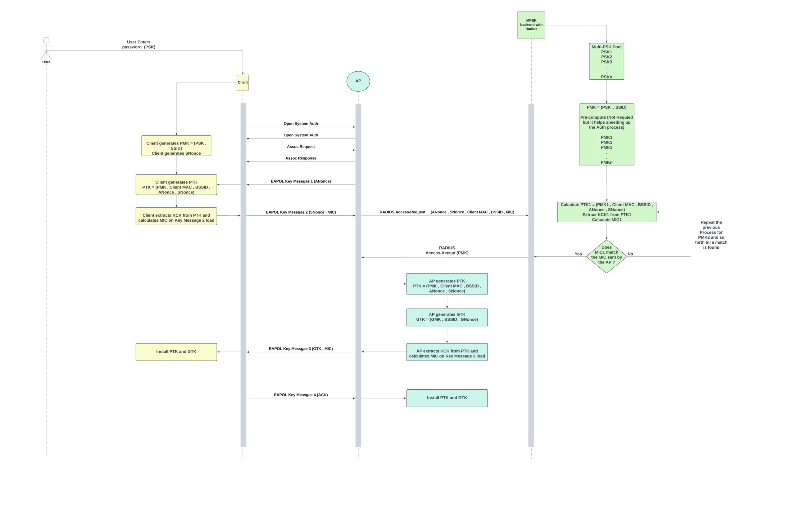
In a traditional MPSK-RADIUS system, the AP does not have knowledge of the passphrase. Instead, a RADIUS server is configured with a list of MAC addresses and their corresponding passphrases. When a new client tries to connect to the AP, it goes through the open system authentication and association processes. Afterward, the AP initiates the 4-way handshake:
The AP sends EAPOL-Key message 1, which contains the ANonce.
The client generates the SNonce and, using it alongside the passphrase (which is expanded based on the SSID to become the PMK, where PMK = f(PSK, SSID)), generates the PTK and its derivatives (KEK, KCK, and TK).
PTK = f(PMK, Client MAC, BSSID, ANonce, SNonce)
The client installs the PTK, constructs EAPOL-Key message 2 by adding the SNonce, and uses the KCK to calculate a MIC for the message payload.
In a typical WPA2 Personal scenario, the AP would use the same inputs to calculate the PTK and verify the MIC based on the KCK. However, since the passphrase is stored on the RADIUS server, the AP forwards the entire content of EAPOL-Key message 2 to the RADIUS server in an Access-Request message.
The RADIUS server searches for a matching MAC address in its list. Once a match is found, it uses the passphrase and the information from EAPOL-Key message 2 to calculate the PMK. The RADIUS server then sends the PMK to the AP in an Access-Accept message.
With the PMK, the AP can either use the existing ANonce and SNonce to calculate the PTK and its derivatives or restart the 4-way handshake procedure to obtain new values. This decision typically depends on the configured timeout between EAPOL-Key messages and the time it takes for the RADIUS server to respond with the Access-Accept message.
The remainder of the process follows the standard 4-way handshake. The AP installs the PTK, generates the GTK (if this is its first client), encrypts it with the PTK, and sends it in EAPOL-Key message 3.
The final message, EAPOL-Key 4, is sent by the client to acknowledge the receipt and installation of the GTK.
This setup works well in controlled environments where the network administrator has a pre-populated list of all client MAC addresses. This scenario is common in enterprise networks where EAP is the primary authentication method, and MPSK-RADIUS is used to onboard IoT devices that do not support 802.1X.
However, a traditional MPSK-RADIUS setup is impractical in environments where the administrator has no control over the devices users bring to the network. A prime example is MDU networks, where the admin needs to manage a pool of PSKs that are not tied to a one-to-one mapping with specific MAC addresses. The system must allow users to authenticate with their assigned PSK, regardless of the MAC address of the device they are using to connect to the network.
MPSK with RADIUS systems offers a solution to the problem mentioned above. These solutions typically consist of multiple components that provide various services. Some of these components include:
RADIUS server for authentication and accounting.
Databases to manage pools of PSKs and PMKs.
Captive portal services for user interaction and onboarding.
SMS gateways to assist with new customer onboarding.
User portal for customers to manage their subscriptions and change their passwords without requiring network admin intervention.
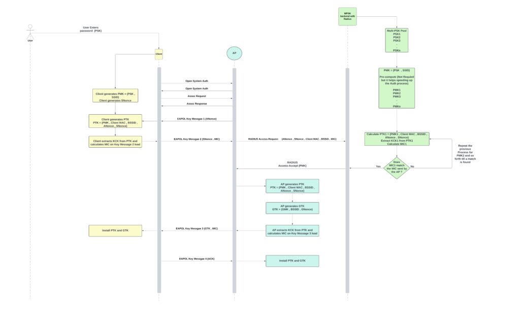
The workflow for an MPSK-RADIUS solution is similar to the traditional MPSK-RADIUS setup described above, with one key difference: instead of matching the MAC address of the authenticating client to a list of one-to-one MAC-to-PSK pairs, the system calculates the PTK and MIC for all PSKs in the pool and tests them against the MIC sent by the AP in EAPOL-Key message 2. When a match is found, the system forwards the corresponding PMK to the AP. Once the AP receives the PMK, it has two options:
Create the GTK and build EAPOL-Key message 3: The AP generates the Group Temporal Key (GTK) if this is the first client or if a new GTK is needed. It then builds EAPOL-Key message 3, encrypts the GTK with the PTK, and sends it to the client.
Restart the 4-way handshake: If the time spent waiting for the Access-Accept message with the PMK exceeds the timeout for the 4-way handshake, the AP will restart the handshake process. This ensures that fresh ANonce and SNonce values are used, allowing the process to complete successfully.
MPSK-Radius solution authentication process
One major downside to the process described in the flowchart above is that every time a device roams to a new AP, it must undergo a full RADIUS authentication, which usually takes about one second. A roaming time of one second is unacceptable, as it can disrupt most Layer 3 (L3) connections. To address this, OpenWiFi enables PMKSA key caching for when the client re-roams back to the original AP and supports Fast Transition (FT) with MPSK-RADIUS or PSK-RADIUS when roaming to a new AP. The FT process can be summarized as follows:
Client initiates the roaming process by scanning for the next best candidate AP.
Client confirms FT support: The client checks whether the target AP supports Over-The-Air (OTA) or Distribution System (DS) FT transition roaming.
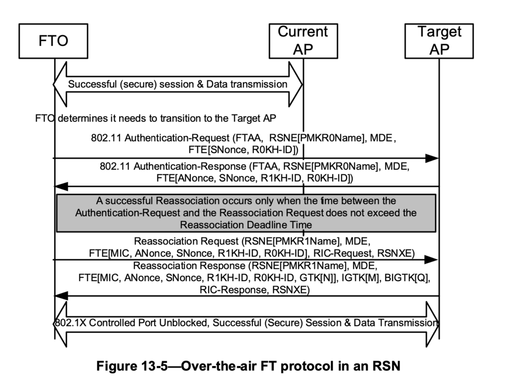
For Over-The-Air (OTA) FT:
Authentication exchange: The client and the target AP exchange FT Authentication frames. The client shares its SNonce, PMK ID, PMK-R0 ID, and Mobility Domain ID with the target AP. In return, the target AP provides its ANonce, PMK ID, PMK-R0 ID, PMK-R1 ID, and Mobility Domain ID.
Association exchange: The client and the target AP exchange Association and Reassociation frames. In the Association frames, the client includes the same information as above, along with a MIC generated on the message payload. In the Reassociation frames, the target AP includes the same information plus the GTK.
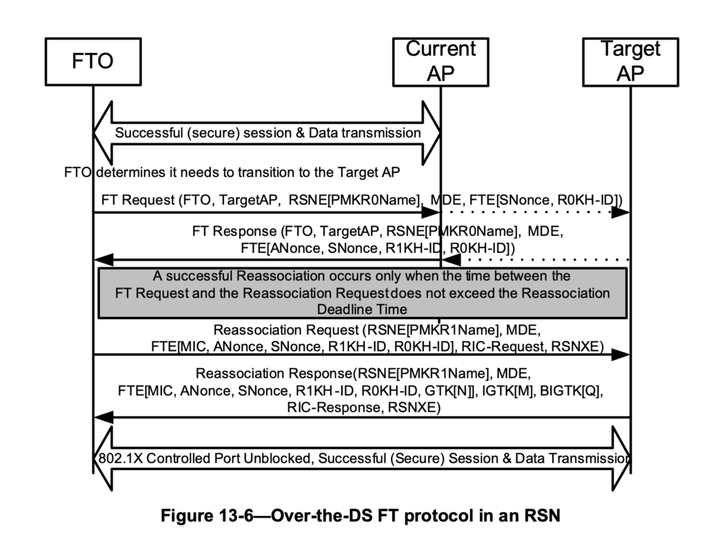
For Distribution System (DS) FT:
Authentication exchange: The same information is exchanged in the Authentication frames as in OTA FT, but instead of being sent over the air, the data is embedded in an Action Frame sent to the current AP. The current AP forwards this frame over the distribution system to the target AP. The target AP replies to the client via the distribution system through the current AP.
Association and Reassociation exchange: The Association and Reassociation frames remain unchanged, and the procedure follows the same steps as in the OTA case.
Flowchart of the OTA FT process from the IEEE802.11 2020 document
Flowchart of over DS FT process from the IEEE802.11 2020 document
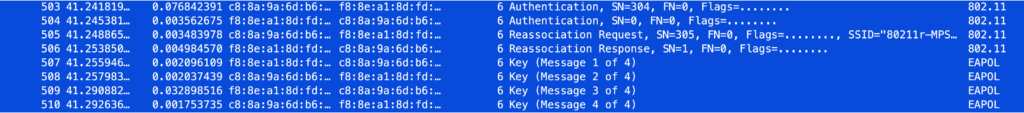
The packet capture screenshots below illustrate how PMKSA key caching and Over-The-Air (OTA) Fast Transition (FT) with MPSK-RADIUS reduce authentication time from approximately 1 second to around 50 milliseconds.
OpenWiFi time with PMKSA Key caching when roaming back to the original AP
OpenWiFi Roaming time with MPSK-Radius with OTA FT enabled.
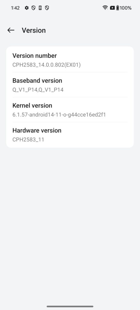
Go to Settings -> About device -> Version, and tap on “Version number” 7 times, this should enable the developer mode.
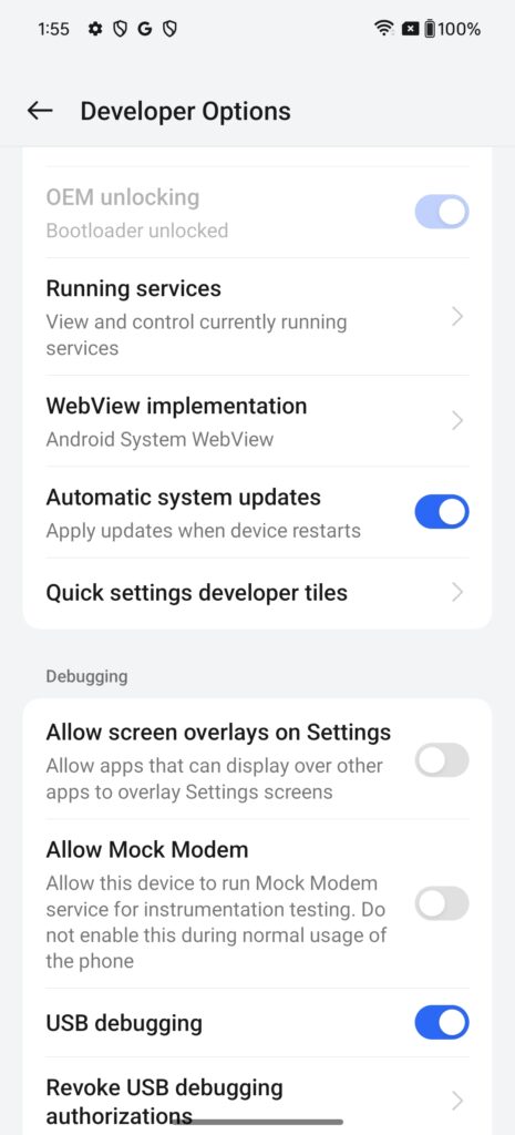
Go to Settings -> Additional settings -> Developer Options, and enable “USB debugging” and “OEM unlocking”.
To communicate with the OnePlus phone we will need to install the command-line tool adb (Android Debug Bridge). On a MacOS this can be installed using HomeBrew.
Connect the device to your laptop using a USB-C to USB-C or USB-C to USB-A cable. Now, you should be able to see your device listed under the connected devices.
firasshaari@MacBook-Pro-9 ~ % adb devices
List of devices attached
76f80f11	device
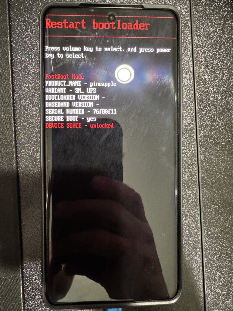
Reboot the device in the bootloader mode using the below command.
Now in the bootloader mode your device should have a similar screen to the photo below except, its bootloader is still in the locked state.
Now using either one of the 2 commands listed below your phone will prompt you that you’re about to unlock the bootloader. Once you accept that, the device will reboot and a message stating that the device cannot be trusted and you will need to set up it again from scratch.
After setting up your device, we will need to install the Magisk APK to allow for super user access on the device. Download Magisk-v27.0.apk and push it your device’s SD card using the following command.
Use the Files app on the device to install the Magisk APK. In my case you can see that the device is trying to update the already installed APK
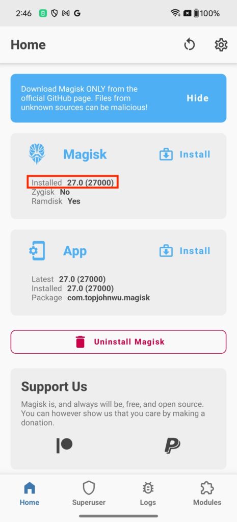
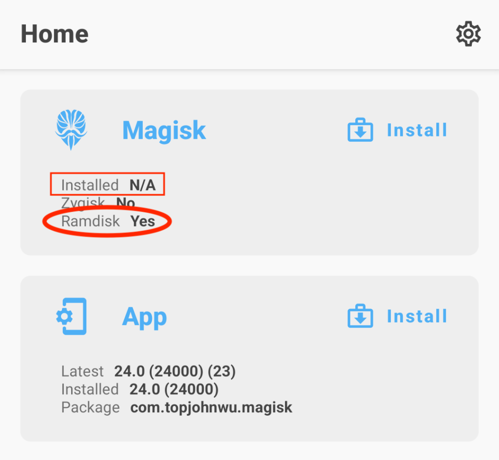
After installing the APK you should be greeted with a similar screen the one below. The only difference between my screenshot and yours will be that you haven’t installed Magisk yet.
We will need to download a FW image for the OnePlus. Pay attenuation to your HW version, since they are different images for different regulatory domains. I found the FW images on this XDA forum post.
I uploaded the North America images to my OneDrive. you can find them in the links below. In my case I used OxygenOS-CPH2583_14.0.0.404(EX01)A.57 image.
Download the Payload Dumper and follow the installation steps in the ReadMe file. This will be used to extract the “init_boot.img” file from the FW image. In my case this version payload-dumper-go_1.2.2_darwin_amd64 worked on my 2023 MacBook Pro 14″.
Copy the “init_boot.img” file to your device using the push command.
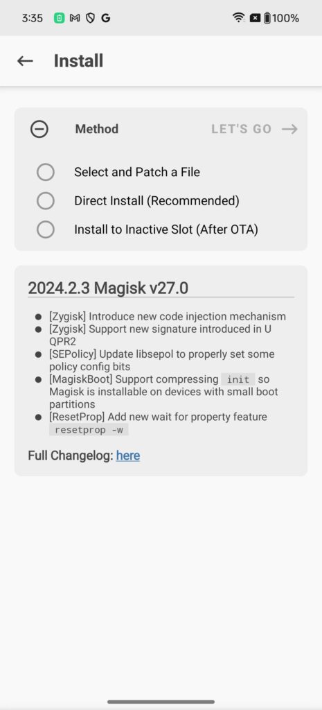
Open Magisk on the device, click on the “Ramdisk” install and “Select and Patch a File” and select the “init_boot.img” file that we pushed to the device in the last step.
Using the adb pull command, pull the generated patched “init_boot.img” file from your phone to your laptop.
Reboot the device and if all goes well Magisk should be installed and, at this point and you should have root access on the device. It can be seen in the example below how running iw commands fails at first but after acquiring root privileges using the su command the command is executed successfully.
firasshaari@MacBook-Pro-9 ~ % adb shell
OP595DL1:/ $ iw wlan info
/system/bin/sh: iw: inaccessible or not found
127|OP595DL1:/ $ su
1|OP595DL1:/ # iw wlan0 info
Interface wlan0
	ifindex 24
	wdev 0x1
	addr 8e:f1:ad:a1:a6:71
	ssid home
	type managed
	wiphy 0
	channel 36 (5180 MHz), width: 80 MHz, center1: 5210 MHz
	txpower 20.00 dBm
OP595DL1:/ #
To turn the OnePlus 12 into sniffer mode, execute the following commands on adb shell.
iw phy phy0 interface add mon0 type monitor
ip link set wlan0 down
ip link set mon0 up
ip link set wlan0 down
iw dev mon0 set channel 36
tcpdump -i mon0 -envvv
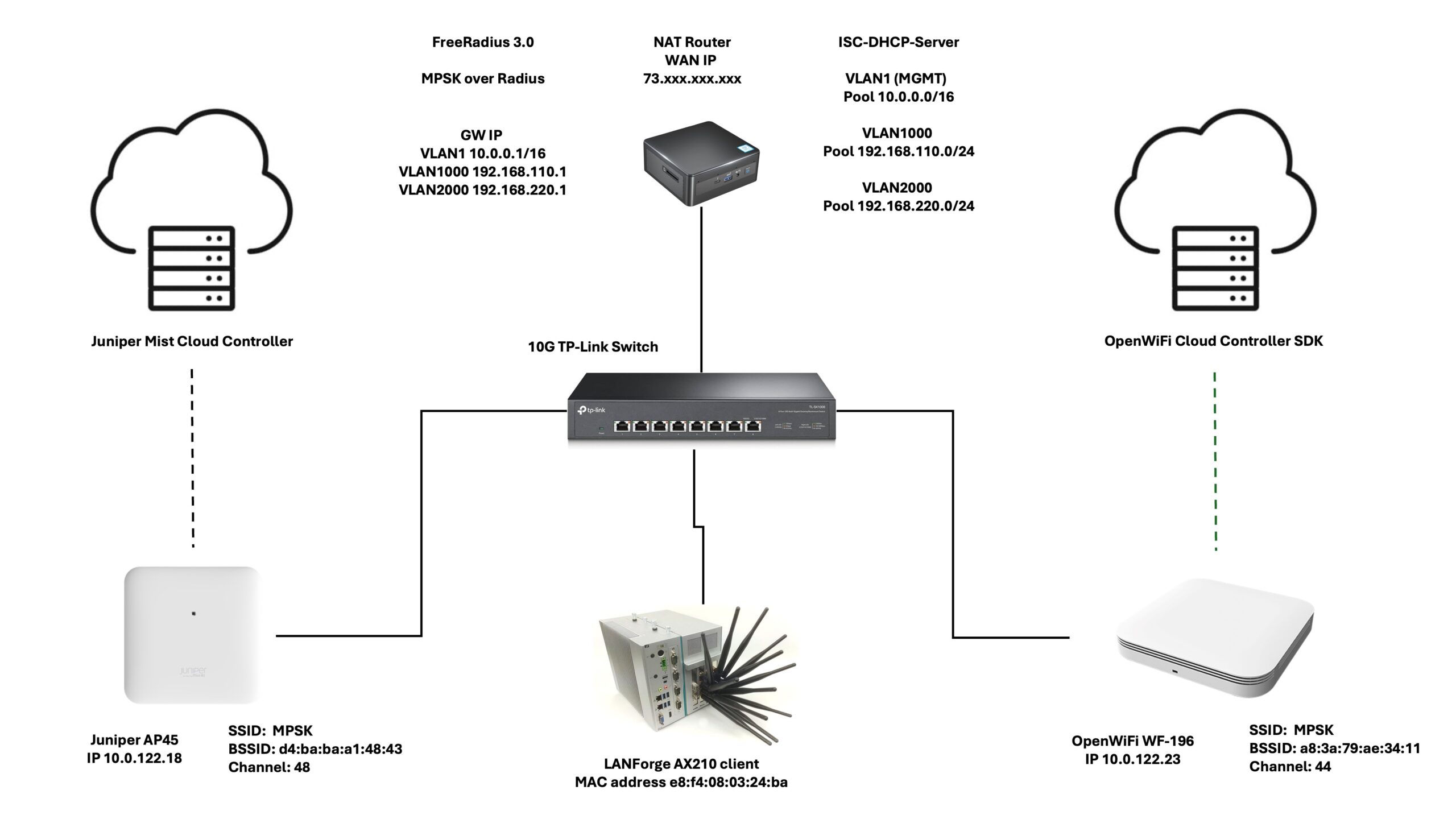
In today’s diverse networking environments, there’s a growing trend towards combining proprietary vendor solutions with open-source alternatives to achieve a balance of reliable performance and cost-effectiveness. This article explores this idea by demonstrating a Multi-Pre-Shared Key (MPSK) Wi-Fi solution using both Juniper APs and OpenWiFi APs, where authentication and accounting is managed through FreeRadius server.
The Network Setup
At the heart of the network, we have the 3.0 version of the FreeRadius server—an open-source solution capable of handling authentication for a variety of devices which I am running on my home NUC Ubuntu box, alongside a ISC-DHCP-Server to handle DHCP requests, and some iptables NAT rules to nat clients to the outside world . In this scenario, we’re looking at the Juniper AP45 and the TIP OpenWiFi CIG WF-196, both are configured through their cloud controller and added as clients within the FreeRadius’s clients.conf file.
For continuous roaming tests between these two APs, the Candela LANforge WiFi Roam test is employed. The test basically allows the user to construct a script that can run for a set amount of time or indefinitely. The operator can determine where, when, and how long the client should roam.
Configuring MPSK
The MPSK configuration requires minimal adjustments on the FreeRadius server. For each device, the MAC address and the PSK are entered into the users file:
# LANforge AX210
e8f4080324ba Cleartext-Password := "e8f4080324ba"
        Tunnel-Type = 13,
        Tunnel-Medium-Type = 6,
        Tunnel-Private-Group-Id = 1000,
        # Expected PSK for OpenWiFi using the tunneled password attribute
        Tunnel-Password = 12345678,
        # Expected PSK for Juniper in a Cisco AVPair attributes
        Cisco-AVPair = "psk-mode=ascii",
        Cisco-AVPair += "psk=12345678"
Notably, TIP OpenWiFi APs require the Tunnel-Password attribute, while the Juniper APs utilize the Cisco-AVPair attributes. The 2 different approaches show case how an homogenous ecosystem can be built by integrating proprietary and open source solutions with a universal authentication system like FreeRadius.
Mixed Ecosystem Benefits
The merger of TIP OpenWiFi and proprietary solutions like Juniper’s APs provides numerous benefits:
Cost Efficiency: TIP OpenWiFi APs like the WF-196 are significantly more affordable than many proprietary solutions and can sometimes be the only realistic solution in industries with limited budget. A simple comparison of the two APs demonstrates why the open source solution might be a game changer for industries where budgets are limited.
Flexibility: TIP OpenWiFi’s open-source nature allows for extensive customization and integration. The open source code allows for customizations that might not be available with the vendor locked solution.
Innovation: Proprietary solutions often come with advanced features and robust support, while open-source projects bring community-driven innovation. As a member of the OpenWiFi community you have the opportunity to lead the development of new features on corner cases that the vendor might not be interested in developing.
Configuraing The OpenWiFi Controller: An SDK with a UI
The OpenWiFi controller stands out as an SDK (Software Development Kit) with a user interface, designed for developers and organizations to create their own user-friendly controllers.below we show a screenshot of the configs in a JSON file format. Not all fields have been expanded to not overwhelm the reader. Only the important parts that highlight the settings for the SSID and the RADIUS server.
The Juniper Controllers Configuration
Configuring the Juniper Controller was straightforward and uncomplicated. As someone who had never used it before, I felt as if I had been using it for years. Every configuration was where you expected it to be, and the transitions between steps were effortless.
Running the Test.
The brief movie below shows a wireless STA managed by the Canddela LANforge roaming between the AP45 (channel 48) and the WF-196 (channel 44). Two additional radios were utilized as sniffers to catch the traffic. An EAPOL display filter was employed to separate the 4-Way Handshake from the rest of the air traffic.
I did not get into the specifics of how to set up a FreeRadius server or the more in-depth aspects of the Juniper Mist MPSK setups because that was not the purpose of this article. If you need assistance with the issues listed above, please see my wonderful friend Mohammad Al‘s post at https://artofrf.com/2024/04/02/mist-mpsk-with-freeradius/.